EE2.sad: Laboratory 1
[ Home | Syllabus | Exercises | Coursework | Exams ]
[
Design activity |
Lab 1: A,B,C |
Lab 2: A,B,C |
Groups ]
Instructions for the first laboratory (groups SQL, VB, XML and Z)
You will not be able to finish the laboratory and the assignment during the supervised session (total 3-4 hrs work), so just try to get the most out of it and make as much headway as you can.
If you've got this far, then you'll have already logged in and opened a browser. The lab contains three exercises:
- Read "Web Engineer on Unix", so you can:
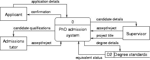
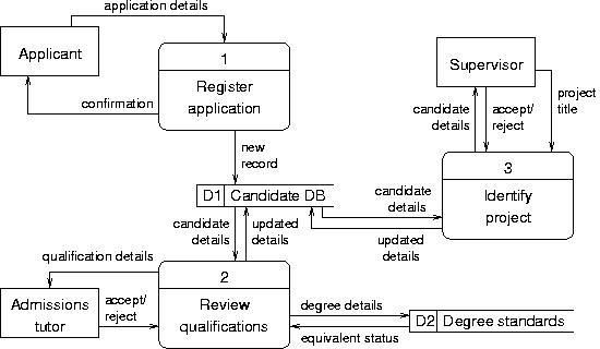
- enter the context diagram for the Research Admissions System (groups SQL, VB, XML and Z) into the CASE tool, and
- complete the level-0 Data Flow Diagram for it.
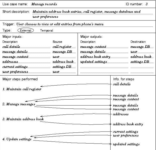
- Sketch DFD fragments for each of the given scenarios (aka. use cases), and compile them into a single DFD describing the operation of a Mobile Phone (groups SQL, VB, XML and Z). Then, put into your CASE repository:
- the context diagram, and
- the level-0 DFD.
- Enter the ERD fragment into the CASE repository, in preparation for the second laboratory.
Your performance will be assessed during the laboratory, but mostly from the completed work that you hand in to me, which should contain: (i) printouts of the context diagram and level-0 data flow diagram for the Admissions System, (ii) the same for the Phone System built up from the scenario descriptions, plus your hand sketches of the DFD fragments, (iii) a printout of the entity relationship diagram for the Admissions System.
You should ensure that all your work for this exercise, including your sketched DFD fragments, is stapled together and has your name clearly marked on it. Your submitted work will be checked against the repository in your file space at the next lab, so make sure you complete the exercise independently (copying or plagiarism will be severely penalised!). Finally, here are some tips that might help you printing.
Submit your assignment to the undergraduate office in the usual way, clearly indicating your name, group and the module code (EE2.sad). For groups SQL, VB, XML and Z, the deadline to submit your coursework is 12 pm on Wednesday 5 Nov.
1. Web Engineer on Unix
- From the [Applications] menu, select [FEPS > Servers > Butters], which opens a terminal window on the machine we're going to use.
- Move the mouse into the terminal window and click to make it active. Create a new directory in you home (top-level) directory, called engineer, using the command mkdir. Check that you can now see it in your home directory, and you should also check you have the hidden directory .logs, which can be seen by listing all the contents of your current directory: "ls -a".
- Type the Unix command "eng &" to invoke Web engineer (the ampersand "&" leaves the first window still active). After a few moments, the main window will appear (which is actually quite small). Put it near a corner of the screen so you can see it while you're working on the diagrams.
- Create a new repository. A dialogue box appears that has a filter on the top line, which displays designs that already exist (i.e., none for you yet). In the middle is shows directories, and at the bottom your chosen filename. Navigate into your engineer directory and call the new file something like lab1. Finally, click on the [Okay] button, which will set up a repository for you to store your software design (actually, a whole new subdirectory).
- A window will pop up, asking if you wish to "import the StartUpKit". This kit contains a number of predefined templates for code generation, which you don't need, so hit [No].
-
Three model windows will appear: Corporate Modelling,
System Modelling and Design and Construction.
We are going to be working with the System Modelling aspects of the
design, so bring this window to the foreground.
From the little tree inside the System Modelling window, right-click on "Models", which should bring up an Operations menu. Select [New system model] which will produce a new entry under Models. Select [Edit], and type in the name of the design that you are about to enter, and click [OK]. The design relates to a research admissions system, in the first exercise, so you might put admiss_sys, for instance.
Drawing a data flow diagram
To open the Data Flow Diagram window: right-click on "admiss_sys" (which is now the model name in the System Modelling window), left-click on the pop-up menu item "show", and left-click on "Data Flow Diagram" in the next pop-up menu. The a brand new window appears where you can draw your DFDs.
General notes on the diagram interface
The general rule within the tool is that the left button selects, and the right button brings up various menus (from which other options can be selected, with the left button).
If you choose to add an element (from the pop-up menu), the cursor will change until have selected a place in the diagram, by left-clicking and dropping the element there.
If you are annotating, writing a label or adding a name to something, you will be given an edit window where you can enter lines of text, including spaces. When you click [OK], the system will check whether it recognizes the name you've typed; if not, it asks whether you'd like to create it. Answering [No] will allow you to choose one from the list of names that are already in the system (this can be useful for linking data flows between different DFD levels).
Some objects belong to other objects - for example, a process can have a name and several data flows. Data flows belong to the source object (viz, external agent, data store or process).
To select an object, point to it and left-click. Note, however, that the name of an object (such as a process) may be on top of the object and almost as large as it. So, you will need to be careful when you are trying to select the object that you don't just select its label. (If the first item on the pop-up menu is "Edit", you've got the name instead!) Finally, you can get a bit stuck if you try to draw a data flow without having a destination object for it! To escape, left-click on the left hand button in the toolbar, Deselect.
Drawing your first diagram
Point to the background, press the right button, select [Add > process] from the menus. Similarly, add two external entities and a data store. Then, select each in turn, and label each one with a name.
For the process, you can put the process number on one line, and the rest of the name below: e.g., "0"<return>, "PhD Admission"<return>, "System". By selecting a process or an external agent, you can draw a data flow from it to some other object.Once a process has been named, you can select it and [Show > Data flow diagram] to take you down to the next DFD level for that process. Here are the context diagram and the level-0 DFD for groups SQL, VB, XML and Z, which you should enter into your repository, as the first exercise (click on the pictures to enlarge):
Saving your work
When you wish to end your session and pack up, make sure you save your work correctly. A number of people just closed all the windows and were surprised when their files were unreadable the next time they went to look at them - yes, you guessed it - and they had to start again from the beginning! You can close the three Modelling windows in the normal ways, but you must close your design repository using the main window.
It will ask if you wish to save your changes or discard them, so select [Save]. A dialogue box inviting comments will appear, and it is good practice to add a brief note here to record the design's development: type in a remark or two (like "Design started context and level-0 DFD"), and hit [Publish], which will store the changes. You can then quit in the usual way, i.e., [File > Exit] and [OK].
Updating your design
When you return to your work and re-open the repository, as a precaution against unintentional alterations, it appears in Read-only mode. So to be able to make any changes, you'll need first to switch mode using the menus, [Edit > Make editable].
2. Converting scenario descriptions into a DFD
The following descriptions were obtained as part of the requirements specification for a mobile phone. You are to derive the system's top level data flow diagrams from the three scenario descriptions in the diagrams below (groups SQL, VB, XML and Z):
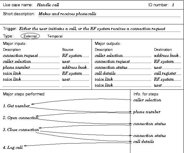
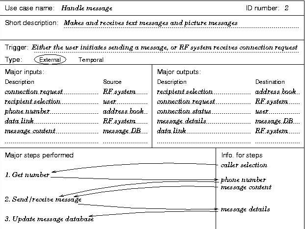
First of all, you should sketch out by hand the DFD fragment that corresponds to each of the scenarios (also called "use cases"). Once you've got all of them, you can put them together in one chart, to give you a sketch of the entire level-0 data flow diagram.
By redrawing the system as a single bubble, with all its data flows to and from the external entities and external data stores, produce the context diagram for this system.
When you come to enter the context diagram and the level-0 DFD into your Web Engineer repository, create a [New system model] and give it an appropriate name (e.g., mobile_phone). You should print off your final version, together with your sketches of the DFD fragments.
3. Drawing an Entity-Relationship Diagram
The aim of this exercise is to build on the use cases (scenario descriptions) and DFDs in the previous two exercises by creating an entity-relationship diagram for the Research Admissions System, shown below (groups SQL, VB, XML and Z):
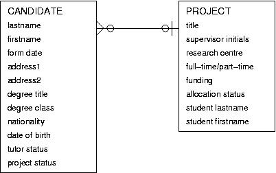
In Web Engineer, open your working repository (created in the previous exercises) and, in the System Modelling window, right-click on the admiss_sys (under Models) and then left-click on [Show > Entity-relationship diagram ]. A new window will appear in which you can reproduce the above ERD.
- Start by adding the two entities and naming them.
- Add their attributes into them. You will need to delete the ".*" in the edit attribute box, before typing the attribute name. Here you must use underscores instead of spaces.
- Enter the domain for each attribute (where the domain is the type) by right-clicking on the attribute and choosing [select domain]. Delete ".*" from the edit box and type string, integer, Boolean, etc., as appropriate.
- Mark the identifier(s) for each entity by right clicking on the relevant attribute(s) and choosing [make identifying].
- Add a relationship between the entity name and its attributes by selecting the entity, right-clicking and choosing [relationship].
- Add the relationships descriptions between the entities, by editing <role 1> and <role 2>. Change the default cardinalities and modalities to the appropriate setting by right-clicking on the relationship name and choosing [change degree].